


From time immemorial communication has been a very important part of human evolution .Since the very beginning of the human population, human beings as well as animals have used various modes of communication(languages and gestures) to share information, convey emotions and share ideas with one another. In computing, the case is not very different as computers, developers and other groups of individuals that work on computer systems use various methods through which they can convey their thoughts and share information. This then brings us to the question of what UML is all about. It is often said that teams that can't communicate software architecture will find it difficult to create a clear starting point to work from.
What is UML?
UML stands for Unified Modelling Language and it is a standardised modelling or visualisation language that was created by the OMG(Object Management Group) with a common goal of providing a semantically and syntactically rich visual modelling language for the architecture, design, and implementation of complex software systems both structurally and behaviourally. It is a pictorial (diagramming) language that is used by developers and other individuals around the world to model software and non-software systems. So to communicate, developers use a variety of UML diagrams that carry unique meanings in various contexts. UML is programming language independent and goes beyond the domain of software development(it is essentially a general purpose language). Now let's look at the various types of UML diagrams.
Types of UML Diagrams
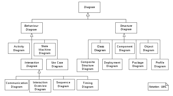
To graphically model software systems, developers make use of a variety of UML diagrams, diagrams that describe the boundary, structure, and the behaviour of a system and the objects that are within it. Since UML diagrams represent both the structural and behavioural view of a system, they have been divided into two sub types which are; Structural and Behavioural diagrams. The structural UML Diagrams include;
- Class Diagram.
- Component Diagram.
- Deployment Diagram.
- Object Diagram.
- Package Diagram.
- Profile Diagram.
- Composite Structure Diagram.
The behavioural diagrams include;
- Use case Diagram.
- Use Case Diagram
- Activity Diagram
- State Machine Diagram
- Sequence Diagram
- Communication Diagram
- Interaction Overview Diagram
- Timing Diagram
As a means to not bug down this article with too much information, we are only going to look at each of the various types of diagrams in brevity.
Structural Diagram
Structural diagrams are used to depict or represent the static view of a system. This static aspect or static view of a system makes up its main structure. The static parts are represented by classes, interfaces, objects, components, and nodes. Now let's look at some of the most common structural diagrams looking at each one in small detail.
Class Diagram
They are the most commonly used diagrams in UML. Class diagram consists of classes, interfaces, associations, and collaboration. Class diagrams fundamentally depict the object-oriented view of a system, which is static in nature. Since class diagrams represent the object oriented aspect of a system, they are generally used for development purposes. They are the most widely used diagrams during a system's development phase.
Component Diagram
Component Diagrams represent how each and every component acts during the execution and running of a system program. They are also used to represent the structure and organisation of all the component as well as show the code modules of a system. They are generally used for modelling subsystems that are part of a larger system. The main purpose of component diagrams is simply to show relationship among various components of a system.
Object Diagram
They are basically screenshots of the instances in a system and the relationship that exists between them. An object diagram is essentially a diagram that shows a complete or partial view of the structure of a modelled system at a specific point in time. An object diagram is similar to a class diagram except it shows the instances of classes in the system. Since they depict behaviour when objects have been instantiated, they make it possible to study the behaviour of the system at a particular time or instant. Object diagrams are vital to portray and understand the functional requirements of a system.Deployment Diagram
Deployment Diagrams are used to represent or model the physical aspects of a software system. Fundamentally, they tell us what hardware components exist and what software components run on them. Deployment diagrams are important for visualising, specifying, and documenting embedded, client/server, and distributed systems and also for managing executable systems through forward and reverse engineering.
Behavioural Diagrams.
Behavioural diagrams are used to visualise, specify or capture the dynamic aspects of a system meaning they are used to visualise a system that is running or being operated upon. I have covered some of the most commonly used behavioural diagrams below.
Use case Diagrams
A use case describes the sequence of actions a system performs yielding visible results. It shows the interaction of things outside the system with the system itself. Use cases may be applied to the whole system as well as a part of the system. It depicts a user's possible interactions with a system. A use case is made up essentially of actors and use cases.
Sequence Diagram
A sequence diagram depicts interaction between objects in a sequential order i.e. the order in which these interactions take place. They are sometimes referred to as event diagrams or event scenarios. They are the most used interaction diagrams.
State Diagram
A state diagram is used to represent the condition of the system or part of the system at finite instances of time. It’s a behavioural diagram that represents behaviour using finite state transitions. State diagrams are also referred to as State machines and State-chart Diagrams. These terms are often used interchangeably. So simply, a state diagram is used to model the dynamic behaviour of a class in response to time and changing external stimuli. We can say that each and every class has a state but we don’t model every class using State diagrams.
Activity Diagram
It is more or less an advanced version of flowchart diagrams that visualises or models the flow from one activity to another. They are used mainly to illustrate the interconnected flow between activities and actions in a system.
What has been covered above is just a sub section of the various types of structural and behavioural diagrams and there is more to all of them, much more than what has been covered. This was just an overview of what they are all about. Now you might be asking why you should use UML to model your projects.
Why you should learn and use UML?
UML plays a vital role in the design and development of software systems, and the fact that is not limited to the design of software systems(it is a general purpose modelling language) makes it much more valuable. Some of the reasons why you should consider learning and using UML are;
- UML is a consistent, universal and standardised method of visualising systems meaning it is used as a standard all over the world to share knowledge and ideas.
- Not everyone involved in the development of a software system understands code so UML provides a means to communicate important aspects such as system requirements, functionalities and processes with non programmers(especially external stakeholders such as investors).
- Complex applications need collaboration and planning from multiple teams and hence require a clear and concise way to communicate amongst them, this concise means of communication is readily provided by UML.
- UML has stood the test of time since it was adopted as a standard by the Object Management Group in 1997.
Conclusion
Learning UML can be quite frustrating or overwhelming at first as there are many concepts that need to be understood, but like with most things in life you get better with practice. If you are looking for more resources to help you grasp the concept of UML better, consider check out this youtube video by FreeCodeCamp.